
How to Use a Multimeter: Beginner's Guide and Common Mistakes

How to Use a Multimeter in 5 Steps
Plug the black lead into COM and the red lead into the jack for what you are measuring (VΩHz for voltage, resistance and continuity; mA or A for current).
Turn the dial to the function: V for voltage, Ω for resistance, the diode symbol for diode and continuity, A for current. Some meters have separate AC and DC positions; on the VC890C, AC and DC share one sector and you press SELECT to switch between them.
On a manual-range meter such as the VC890C, pick the lowest range that is still higher than the value you expect. If you do not know what to expect, start at the highest range and step down. An auto-range meter selects the range for you.
Touch the probes to the circuit: across the part (in parallel) for voltage and resistance, in the path of the current (in series) for current. Power must be off for resistance, continuity, diode and capacitance.
Read the display. "OL" means the value is above the selected range or the circuit is open: move up one range, and if it still shows "OL" the circuit or part is open.
The rest of this guide walks through each function in detail, then covers everyday tests (battery, outlet, fuse, wire), safety rules, troubleshooting and the mistakes beginners make most often.
Why This Guide Exists
Most beginners only use multimeters for basic voltage testing, fearing damage or shock. This guide simplifies multimeter use, teaching you to confidently use all key functions with step-by-step instructions.
You’ll learn:
3-minute multimeter panel overview
Safe lead placement for all measurements
9 essential functions with clear steps
Critical safety rules and troubleshooting
Maintenance tips for longevity
Part 1: Know Your Multimeter (3-Minute Overview)
Most DMMs share a basic layout. We use VC890C (beginner-friendly) as an example—principles apply to all major brands.
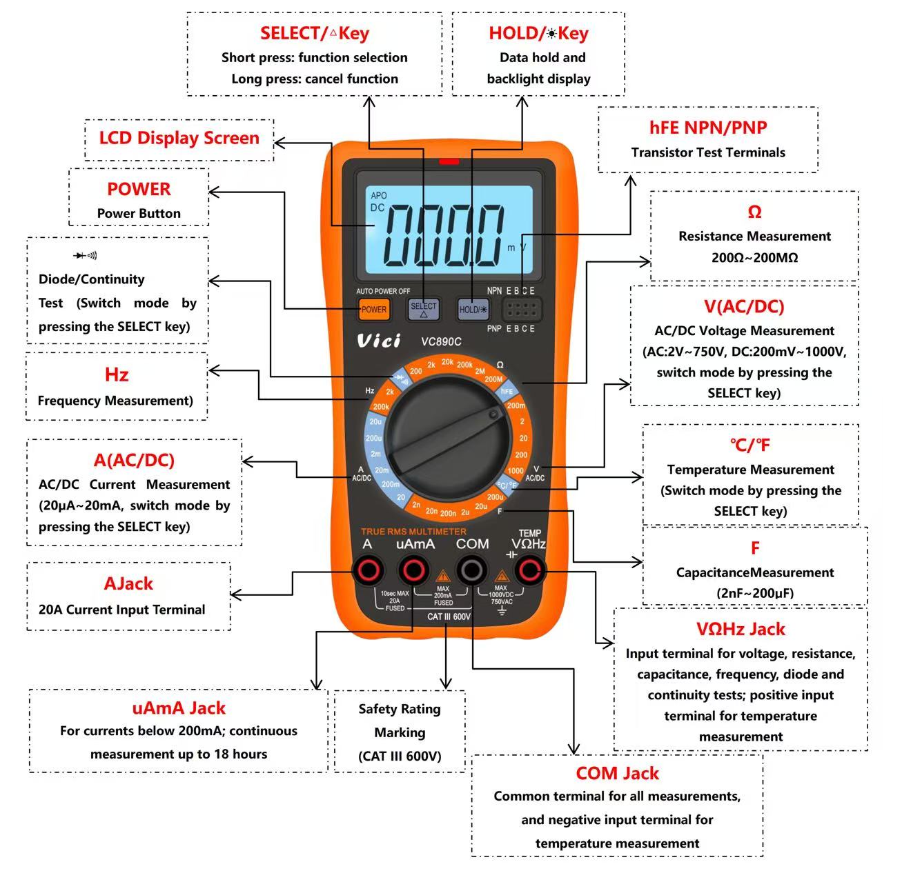
1.1 Four Critical Jacks
Golden Rule: Black lead always in COM (common ground). Red lead moves with the function.
Jack Label | Primary Use | Critical Limit |
COM | Black lead (stays in COM) | Never move black lead from COM |
VΩHz | Voltage, resistance, continuity, capacitance, frequency, diode, temperature | Max 1000V DC / 750V AC |
uA / mA | Small current (DC/AC) | Max 200mA (exceed = blown fuse) |
A | Large current (DC/AC) | Max 20A (10 seconds max per measurement, as marked on the jack) |
Also check the safety rating printed near the jacks. The VC890C is rated CAT III 600V: it is meant for building wiring such as outlets and distribution boards up to 600V. The rating limits where the meter may be used, separately from its 1000V DC range. See CAT III vs CAT IV multimeters for what each category covers.
1.2 Rotary Switch Functions
Quick reference for function symbols:
Function | Measures | Use Case |
AC/DC V | AC/DC voltage | Batteries, outlets, chargers |
Ω (Ohms) | Resistance | Resistors, open circuits |
Diode  | Diode voltage, continuity | Diodes, PCB traces, shorts |
F | Capacitance | Capacitor testing |
Hz | Frequency | Circuits, inverters |
hFE | Transistor gain | Transistor testing |
℃ / ℉ | Temperature (K-type thermocouple) | Heat sinks, soldering irons |
AC/DC A | AC/DC current | Power draw, circuit load |
1.3 Button Functions (VC890C)
Button | Short Press | Long Press | Use |
POWER | — | On/off (auto-sleep after 15min) | Power control |
SELECT | Switch AC/DC, modes | Cancel function | Mode selection |
HOLD | Freeze reading | Backlight on/off | Reading capture, low-light use |
REL | Zero baseline | — | Accurate readings |
Part 2: 9 Essential Multimeter Functions (Step-by-Step)
Note: Black lead = COM; red lead = VΩHz (unless stated otherwise).
2.1 DC / AC Voltage (V)
Use: Batteries, outlets, chargers (most common function).
Turn the dial to the V sector and choose a range higher than the expected voltage. On the VC890C (ACV ranges 2V/20V/200V/750V, DCV ranges 200mV/2V/20V/200V/1000V) the sector is marked 200m/2/20/200/1000: use the top position for 120V or 230V wall outlets (its AC limit is 750V), 2 for a 1.5V cell and 20 for 9V and 12V batteries.
Press SELECT to choose AC (outlets) or DC (batteries); check the AC or DC sign on the display.
Connect leads in parallel to measurement points (red to positive, black to negative for DC; no polarity for AC).
Read display; adjust range if "OL" appears (over-range).
Manual or auto range, and whether you need True RMS for AC readings, is covered in True RMS vs average-responding multimeters. The VC890C is a True RMS, manual-range meter with a 2000-count display; multimeter counts explained shows what that means for resolution.
Safety: Max 1000V DC / 750V AC input; safety rating CAT III 600V. Never touch the metal probe tips while measuring any live circuit, including 120V and 230V outlets. Keep your fingers behind the finger guards.
2.2 DC / AC Current (A)
Use: Power draw, charging current (critical wiring!).
Wiring: Small current (<200mA) → uA/mA jack; Large current (200mA–20A) → A jack.
Set to AC/DC A; select a range higher than the expected current.
Press SELECT to choose AC/DC (match the current type).
Disconnect circuit (break current path) to avoid short circuits.
Connect meter in series with the circuit (red to positive side of the break, black to negative side).
Reconnect power and read; on the 20A range disconnect within 10 seconds.
Never connect the current jacks in parallel across a voltage source: this blows the fuse at once. On the 20A range, keep each measurement under 10 seconds to prevent overheating.
2.3 Resistance (Ω)
Use: Resistors, continuity, open circuits.
Set to Ω (start with highest range if unknown resistor value).
Power off circuit and discharge capacitors (critical to avoid meter damage).
Touch leads to resistor ends (polarity doesn’t matter); wait 1–2 seconds for stable reading.
Read display; adjust to lower range for more accuracy if needed.
Notes: >1MΩ readings are slow (normal). “OL” = over-range or open circuit.
2.4 Capacitance (F)
Use: Testing electrolytic/ceramic/film capacitors.
Set to F range; select a range higher than the capacitor’s rated value.
Press REL to zero lead capacitance (eliminates lead interference).
Fully discharge capacitor (critical—use a resistor to discharge high-capacity capacitors).
Connect leads (red to positive, black to negative for electrolytic capacitors; no polarity for non-polarized).
Read display and compare it with the value and tolerance printed on the capacitor (often ±5%, ±10% or ±20%). A reading outside the tolerance band points to a faulty or aged capacitor. The VC890C measures from a 2nF range up to 200μF.
Safety: Never measure capacitance on live circuits (destroys meter).
2.5 Diode & Continuity
Use: Diodes, PCB traces, shorts/opens.
Turn the dial to the diode/continuity position.
Press SELECT: Diode mode (measures forward voltage) or Continuity (beeps when resistance <50Ω).
Diodes: Red → anode (+), black → cathode (-); reverse leads to check for reverse leakage (should show "OL").
Continuity: Touch leads to wire/trace/solder joint; no beep indicates an open circuit.
Results: Good diode = 0.5–0.7V (forward), “OL” (reverse); Good continuity = beep.
Never apply voltage in this mode (damages meter).
2.6 Temperature (℃/℉)
Requires: K-type thermocouple (red→VΩHz, black→COM).
Use: Heat sinks, motors, soldering irons.
Set the dial to the ℃/℉ position.
Connect K-type thermocouple (red/+ to VΩHz, black/- to COM; ensure secure connection).
Touch probe tip firmly to measurement surface (avoid air gaps for accuracy).
Press SELECT to switch between Celsius (℃) and Fahrenheit (℉); wait 2–3 seconds for stable reading.
2.7 Frequency (Hz)
Use: Square waves, PWM, clock signals, inverters.
Turn the dial to the Hz range above the expected frequency (2kHz or 200kHz on the VC890C).
Red lead to signal source (e.g., circuit pin), black lead to circuit ground (COM).
Read display; use shielded leads for weak signals to reduce noise and improve accuracy.
2.8 Transistor hFE
Use: NPN/PNP transistor gain testing.
Turn the dial to the hFE position.
Identify whether the transistor is NPN or PNP, then insert its pins into the matching E (Emitter), B (Base), C (Collector) holes in the NPN or PNP row of the test socket.
Read gain (β) value and compare it with the hFE range in the transistor's datasheet. Gain differs widely between transistor types, from tens to several hundred, so there is no single "good" number. A reading of zero, or one far outside the datasheet range, points to a damaged transistor.
Note: hFE readings from a multimeter socket are approximate.
Everyday Tests: Battery, Outlet, Fuse and Wire
How to Test a Battery with a Multimeter
Black lead in COM, red lead in VΩHz; turn the dial to the V sector and press SELECT until DC shows on the display. On the VC890C use the 2V range for a single 1.5V AA or AAA cell and the 20V range for 9V and 12V batteries.
Touch red to the + terminal and black to the − terminal.
A fresh alkaline AA or AAA cell reads about 1.5V to 1.6V. A 12V lead-acid car battery at rest reads about 12.6V when fully charged; noticeably lower means it needs charging or testing under load.
How to Test an Outlet with a Multimeter
Check the meter's safety rating first (the VC890C is CAT III 600V) and inspect the leads for cracks or exposed metal.
Black lead in COM, red lead in VΩHz; on the VC890C turn the dial to the top V position (1000; AC limit 750V) and press SELECT until AC shows on the display. In DC mode a live AC outlet can read close to 0V, so always confirm AC before trusting the reading.
Insert the black probe into the neutral slot first, then the red probe into the live (hot) slot. Hold both probes behind the finger guards.
Expect around 120V in North America or around 230V in most of Europe, Asia and Africa. Remove the red probe first, then the black.
How to Test a Fuse
Switch off and remove the fuse from the circuit; testing it in place can give a false reading through other parts.
Turn the dial to the diode/continuity position and press SELECT until the continuity (buzzer) symbol shows.
Touch one probe to each end cap. A beep (below about 50Ω on the VC890C) means the fuse is good; "OL" means it is blown.
How to Check a Wire or Cable for Continuity
Unplug or disconnect the cable so that no voltage is present.
Set continuity mode and touch the probes together first: the meter should beep.
Touch one probe to each end of the same conductor. A beep means the conductor is intact; no beep means a break. Check between different conductors as well: a beep there means a short.
Part 3: 6 Critical Safety Rules
# | Rule | Consequence |
1 | No voltage measurement in current mode | Blown fuse, meter damage |
2 | No voltage in Ω/diode/capacitance/temperature modes | Internal circuit damage |
3 | Never touch metal probe tips on a live circuit; keep fingers behind the finger guards | Electric shock |
4 | 20A measurements 10 seconds max | Overheating, damage |
5 | Power off/discharge capacitors for Ω/capacitance | Meter/circuit damage |
6 | Replace low battery immediately | Inaccurate, misleading readings |
Part 4: Quick Troubleshooting
Problem | Cause | Fix |
No display | Dead battery, or auto power-off after about 15 minutes | Switch the meter on with POWER; replace the two AAA batteries if the screen stays blank |
No current reading | Blown fuse | Replace with same-spec fuse |
Unstable readings | Low battery, poor probe contact | Replace battery, re-seat leads |
“OL” on display | Over-range, open circuit, charged capacitor | Increase range, discharge capacitor |
Continuous beeping (continuity mode) | Probe contact, short circuit | Separate probes, check circuit |
Part 5: Maintenance & Longevity
Keep dry: Store the meter in a cool, dry place away from damp conditions.
Clean gently: Wipe the case with a soft, damp cloth; no alcohol or solvents.
Correct fuses: Replace a blown fuse only with one of the same size, current and voltage rating.
Remove batteries: Take them out if the meter will be stored for more than 3 months, to prevent leakage.
Handle carefully: Keep the meter in its holster and avoid drops and impacts.
Most Common Beginner Mistakes
Leaving the red lead in the A or mA jack after a current test, then measuring voltage. This shorts the source through the meter and blows the fuse. Move the red lead back to VΩHz every time.
Measuring resistance or continuity on a powered circuit. Readings are wrong and the meter can be damaged. Switch off and discharge capacitors first.
Choosing a range below the expected value on a manual-range meter and reading "OL" as a fault. Start high and step down.
Using a meter outside its safety category, for example a CAT II meter on a distribution board. Check the CAT rating against the circuit.
Trusting readings with a low battery. The VC890C shows a low-battery indication below about 2.4V; replace the two AAA cells when it appears.
Choosing a Multimeter
For electronics, appliance and HVAC work, the main choices are display counts (2000 vs 6000 vs 20000 counts), True RMS and auto or manual ranging (True RMS and range guide), and the safety category (CAT III vs CAT IV). If most of your work is current on live conductors, a clamp meter may suit better: see clamp meter vs multimeter. The full range is on our digital multimeters page.
Part 6: Quick Summary
Black to COM, red follows function. Voltage in parallel, current in series. Power off for resistance and capacitance. High voltage: don't touch tips. Large current: 10 seconds max. Diode and temperature modes: no voltage allowed.
Frequently Asked Questions
What setting do I use to test a battery?
DC voltage. On the VC890C turn to the V sector, press SELECT until DC shows, and pick the lowest range above the battery voltage: 2V for a 1.5V AA or AAA cell, 20V for 9V and 12V batteries.
Can I test a wall outlet with a multimeter?
Yes, on AC voltage with a meter rated for the circuit. The VC890C is CAT III 600V; turn to the top V position (AC limit 750V), press SELECT until AC shows, keep fingers behind the finger guards and never touch the probe tips.
What does "OL" mean on a multimeter?
Over limit: the value is above the selected range, or the circuit is open. When measuring a voltage or a component you know is intact, move up one range. In a continuity or resistance test on a wire or fuse, "OL" means there is a break or the fuse is blown.
Why does my multimeter read zero in current mode?
The current fuse is usually blown, often after measuring voltage with the red lead still in the A or mA jack. Replace it with a fuse of the same rating.
Do I need an auto-range multimeter as a beginner?
No. A manual-range meter such as the VC890C teaches you to estimate the value before measuring, which is a good habit. Auto-range is faster when you measure many unknown values; see the range guide.